Eastern Box Turtle
High Elevation Study
Equipment And Methods Used for Radio Telemetry
3 Element Yagi Tracking Antenna
Inexpensive Radio Receiver Options
Tracking "Tricks"
Other equipment
Here's how to build this 3 element yagi antenna in a much more useful configuration for use in wildlife telemetry, using the basic  features of the original  design.  The cost is next to nothing, it is repairable, even in the field, foldable for transport in small spaces, and stays intact when used in heavy brush.  This antenna will point within 10" or so of your target turtle .

Firstly download this PDF to understand the basics of the project:  TAPE MEASURE BEAM OPTIMIZED FOR RADIO DIRECTION FINDING

Secondly, collect the materials.  Most are hardware store or salvage items, except the cable which has a female BNC connector on one end.  If you buy a 12 foot cable with BNC connectors on both ends, cut it in half and make 2 antennas.  The tape measure is a standard 1 inch wide steel type, not the super wide super duty 2 inch one.  This makes a difference.  There is enough length in a 50ft tape to make several antennas with some left over for occasional  repairs.

Two sizes of PCV pipe are needed, but no T's or other connectors from the original design are necessary.   Cut three pieces of 21mm PVC to about 8" each.  Cut one piece of 16mm PVC about 3 foot long to use as the center boom.  

Mark the centers of the 21mm pieces and drill holes all the way through.  Don't ream the holes as you want them to be tight.   Feed the boom pipe through these holes and confirm they can be aligned parallel by setting the whole boom on a flat floor or table.

The cross pieces are going to be glued after properly spacing them (as per below), and making sure they are perfectly parallel by working on a flat surface while the glue sets (3 or 4 seconds each cross).
The hose clamps in this photo will not be retained in the final product, (they catch on every limb and twig) but are very handy for aligning the elements before attaching them permanently with plastic electrical tape.

The copper wire in the photo is much better replaced with a 5" piece of insulated heavy copper house wire.  It's going to be soldered to the ends of the 2 active elements, so heavily tin the stripped ends.

The exposed copper ends of the cable will also be soldered so tin them, too.
Cutting the steel tape can be done with kitchen shears.  The lengths of each are critical, and so is the spacing between them.  Here's where you have to do some math.

The measurements in the drawing to the left are for use at 146.565 Mhz.  If the center of your telemetry frequencies is, say 150.000 MHZ all measurements have to be adjusted by 146.565/150.000 = 0.9771

A reflector for 150MHZ would be
41.375 x 0.9771 =  40.4275"
first spacing would  be
8.0 x 0.9771 = 7.8168"

Remember, higher frequency = shorter antenna measurements

Space the cross pieces as per the new measurements, and accurately glue (using PVC cement) in place on a flat surface making sure the cross pieces are all parallel to each other.

(HINT:  after glue sets, drill holes through both pipes at each intersection, and force in small wooden dowels to keep alignment if glue breaks)
After all steel tape pieces are cut to length, do yourself a favor, and sand and tin the inside ends of the active (middle) elements before assembly.  The wire hairpin and the cable ends will be soldered onto the steel tape before finally securing onto the cross piece.  Don't scrimp on the amount of solder.
Now element assembly starts.

Find the exact centers of the steel tape elements and also put pencil marks on the exact centers of the cross pieces.  Loosely assemble all elements onto the boom, and loosely clamp in place with hose clamps, and adjust the elements parallel by eye.  A ruler to measure end separation helps at this point also.

Using a square or a home-made squaring jig adjust each element perpendicular to the boom and parallel to each other.  Snug the clamps a little as you go until everything seems satisfactory, and then tighten clamps.  Use a plastic electric tape to permanently secure the elements to the crosses on each side of the boom.  Tape the sharp ends of each steel tape element.  The hose clamps should no longer be needed.  They hang up on every branch and twig when tracking!

Secure the wire hairpin to the boom with tape, and also hotglue and tape over the soldered connections.

The cable needs to be secured to the boom, and some sort of comfortable handle, i.e. foam rubber or leather wrap, needs to be secured over ths boom, preferably also over the cable.
These radios have been proven to be very good for telemetry.  All are old  (25 year old since new) Radioshack scanners (although scanning and searching is never used for telemetry), that are cheaply available on Ebay, and all have similar specifications.  All are field programmable, have 0.5uv sensitivity, plastic cases, use 4 AA batteries, and have BNC antenna connectors.  The Pro-28 and Pro-66  display the channel number along with the frequency.  Most others show the channel number but the frequency is only available by pressing the "review" button.  User manuals for each model are available on the web.

Tracking using any of these radios is initially started with squelch off (noisy), but as the range to the target transmitter decreases, turning squelch on is necessary to decrease sensitivity.  There is no BFO, (so no beeping), and scanning and search functions are never used when tracking.  The Pro-49 (about $15)  is good to loan to volunteers:  buttons can be easily disabled by putting tape on the circuit board under each button to disable scan, viewing frequencies, weather, etc. so the small screen is forced to display only the channel number.
Name

Subject


Message


Email Contact
Top of Page
 
Mapping and Data Collection Page
Philosophy and Methodology
Radios and RF Transistors
Box Turtle Fitness Index

DOCUMENT LINKS


Transient Identification
Charts and Graphs
These photos show the wire hairpin and cable soldered in place as well as the homemade element alignment square (I make a new antenna every year).  This antenna has already been aligned and the elements taped in place with electrical tape.  The small piece of wooden dowl can be seen.
Telemetry (tracking) Receivers
These inexpensive 25 year old Radioshack scanners have several advantages over the "professional"  radios, in addition to price.  Each is lightweight and simple to operate (press"Manual" continuously to desired channel or channel # then "Manual").  Each is easily programmable in the field (press desired channel #, press "Manual", press "Clear", enter frequency, press "Enter").  All work very well using high capacity 2600mah Li-ion rechargeable AA batteries.

All also have a "Weather" button, break-resistant plastic cases (from experience), and earphone, power, and charging jacks if these are desired. One very important addition is "required":  put a strip of duct-tape across the top of the battery compartment door (in the back) so it's not lost when dropped....the door will now simply flip up to change batteries.
Tracking Using Yagi Antennas
Most wildlife and Ham Radio fox hunting telemetry operates near the 2-meter band, so best reception should be when the antenna is kept at either 1 (one) or 2 (two) meters above the ground.  Transmitters at long range are better heard when the antenna is kept horizontal, and closer transmitters are best heard when the antenna elements are vertical.

When searching, try all antenna positions, including holding the antenna so the elements are at 45 degrees.  Searching late in the day, or the day after a rain is sometimes more successful than in the heat of the day.  MOVE! (don't just stand in one place)  Even a few feet left or right will sometimes help greatly in getting a signal.

Any Yagi antenna will receive transmitter signals from the rear as well as from the front.  Holding the antenna nearly vertical when close to a turtle signal.....pointing down toward the ground... can usually sort out if the signal is coming from in front of, or in back of the antenna.
Tracking "Tricks" Using this Equipment

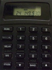
This may work using other radios, but since the RadioShack Pro-28 and Pro-66 have all the sensitivity and functions needed for efficient tracking, these radios are being used for these examples.

Locating a transmitter requires the weakest signal that can be heard when directing the tracking antenna toward the transmitter, and not heard at all when directing away.  The closer the receiver gets to the transmitter, the greater  chance the signal can be heard, but when too close, the antenna and radio will be overwhelmed with the signal appearing to come from all directions.

Always start with the radio's squelch set at minimum (maximum noise).  If a good signal is heard, slowly add some squelch.  If the signal turns to "clicks", keep increasing squelch while tracking.   If you are lucky,  this will work well up to the point where signal comes from all directions even at maximum squelch.

At this point try unplugging the antenna and putting it aside, and turning the squelch OFF at first.....if there is a signal, the transmitter (turtle) is probably nearby, and usually within sight if not hidden under leaves or in hibernation.  This is the time to watch your step and look around!  At hibernation time, sit down and wave the bare radio around at ground level..this usually works to pinpoint a buried turtle, and is also used to find a lost radio in the leaves and long grass.

Using the above method, with practice, tracking can usually be done at walking pace, and the vast majority of my turtles are located this way.  (Over 11,000 locations so far)    As long as some sort of signal can be heard, very good or very bad, the above tracking method works.

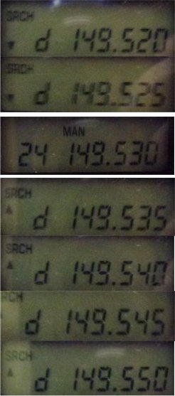
There are common, but odd sounding occassions when there is too much signal, even when using an antenna-less radio with full squelch, to pinpoint a transmitter.  It can take a very long time trampling down brush and grass and digging through soil and roots if this is the case.  This is one instance where "Offset Tuning" comes in.  Basicaly, a radio that is not tuned precisely to a transmitter frequency will have a weak signal.....or none at all.
This is the entire front panel of the Pro-28. Several buttons have dual uses, and many buttons are not used in tracking at all.  The"manual" button is most used, and scan, delay, S/S, and Band are never used.

The "up" and "Down" buttons on the bottom row are used when the radio is in "Search" mode (never used) and are the basis for this trick.

The radio will not search on it's own as long as the squelch is turned "off".
Start Here For this example, 149.530 mhz, which is channel 24 on my radio is used.  Get to CH24 and this display by pressing "2", "4", and "Manual" buttons in order.  Turn off the squelch.
Press the "UP" button twice to get into search mode and increase the received frequency to 149.535 mhz
Press the UP" button again to change the frequency to 149.540 mhz.  Do you still hear a strong signal?
And once more to change to 149.545 mhz, this is an offset of 0.015 mhz
At some point, the "offset" from the programmed frequency becomes too great, and no signal wll be heard.  So go back at least one step to get back to a weak signal.
This display shows a negative offset of 0.010 mhz.  Get here by pressing the "Down" Button.
Offset Tuning
An Example
This method works with any telemetry transmitter, even the $200 commercial ones.  Offsetting the frequency can appear to make the radio super sensitive, but the opposite is actually occurring.  It may not be used on every tracking occassion, but is priceless to know when it's needed, and has saved many hours of work.
For the Technically Minded

The Pro-28 is easily disassembled, and so a very useful modification could be made with little expense or trouble.  This radio's scan speed is much too fast to be useful for tracking.  Manually scanning all 30 channels is simple. With the squelch tuned off, just keep pressing the "Manual" or "Scan" button, and the radio will increment though every channel, and cycle around to channel 1 again.   About 2 or 3 seconds on each programmed channel is usually about right for searching for 1 second transmitter signals.

If a tiny 555 timer and relay is installed inside the radio connected to the "manual" or "scan" button, the radio can be set on continuous scan at a slow rate.  This is not very usefull when tracking a turtle, but is usefull when checking what transmitters are in range at any point and time.
With the weakest signal that can still be heard, the directionality of the antenna is at it's greatest, and this it true when  the antenna is removed also.
Pressing the "Down" button decrements (detunes) the frequency by 0.05mhz on each button press.
 
Home

AOR   AR-8000
1000 Channel, all band, professional scanner
Very expensive
Complicated to program
One of the "standard" tracking radios
Zero Db to Infinity Attenuator
These are the buttons to modify for auto scanning.  The bottom board is lifted out after removing the metal shield without having to unplug any wires. Even the speaker comes out attached to the board. Don't leave skin oils on the button push pads.
The red dots mark the solder pads for the "scan" and "up" buttons The carbon coating needs to be scratched down to the copper foil and fluxed for wires to be soldered on.
The power switch is on the top board, and the (marked) solder connections are on the under-side. The radio batteries power the auto-timer so the switch turns timer power off when the radio is off so they don't run down the batteries....just in case.  The timers DO have their own on-off pushbutton switches, though.
Pro-28 Scanner Modifications for Auto-scanning and Auto-frequency Increment    (Photos can be saved for larger version)
To test the wiring prior to adding the timers, the radio has to be fully assembled, so it's best to run the wires out  through the belt-clip screw holes.  There are 6 wires: 2 for the "scan" button, 2 for the "up" button, and 2 for - and + battery, switched.  Shorting the button wires with the radio turned on is the same as pressing the button.   The 2 power wires are the same as battery voltage (so protect them from shorting).
 
 
This page is under construction
Page 56
Terrapene carolina carolina
A Relict Population Doomed To Extinction?
Incidentlly, not all scanners have "up" and "down" arrow buttons, and of those that do, they are often used to change channels, or otherwise used in search mode, and don't serve the function to increment the desired channel frequency.  If this is the case, an attenuator can be used, or frequency offsets can be programmed into adjacent channels with a little work.

Also, these Radioshack scanners do not display channel names along with the channel frequency, only channel numbers, so those who name their turtles are out of luck.  Professional scanners like the AR8000 can display alpha characters, though.
Auto-incrementing a channel's frequency may not appear to be too useful, but it's use to find the transmit frequency of a transmitter when it's not already known is very helpful.
This page is under construction
PRO-49 10-Channel Programmable 8.10 oz (230 g) 0.5 microV Sensitivity 4-AA Batteries (6.0 VDC)
PRO-27 20-Channel Programmable 8.10 oz (230 g) 0.5 microV Sensitivity 4-AA Batteries (6.0 VDC)
PRO-24 16-Channel Programmable 8.10 oz (230 g) 0.5 microV Sensitivity 4-AA Batteries (6.0 VDC)
PRO-28 30-Channel Programmable 8.8 oz (250 g) 0.5 microV Sensitivity 4-AA Batteries (6.0 VDC)
PRO-66 50-channel Programmable 8.8 oz (250 g) 0.5 microV Sensitivity 4-AA Batteries (6.0 VDC)
PRO-51 200-ChannelProgrammable                                                     4-AA Batteries (6.0 VDC)


Home
2018 Summer
2018 Hibernation
2019 Summer
2019 Hibernation
2020 Summer
2020 Hibernation
2021 Summer
2021 Hibernation
2022 Summer
Meeting and Mating
Turtle Catalog
M17 Superturtle
Land Use History
Odds and Ends
The Bottom Line
Thread Trailing
Processing
Observations
2008-2024