Tracking Transmitter Construction
This page describes how I construct my backup transmitters. It is meant to be understood by persons with at least a little technical electronics knowledge. This is how I do it.....I am sure there are better, faster methods, but I don't have access to any but the basic tools, etc. There is a surface mount version using the same methods and values that performs the same.
This page is not meant to be a step-by-step kit construction, but they DO work first-time every-time for me, and it is a simple circuit using off-the-shelf components. The board and foil pattern can be changed to almost any shape and size.
(A surface mount version would take up a fraction of the board space, maybe making room for a second battery, a 3 volt version.
The board is cheap single sided copper foil board.....any thickness will do. Cut the disks out with a hole saw on a drill press after removing the pilot bit first.
This is a drilled master disk I use as a template for all hole drilling. The holes are drilled first then the foil is etched, when using this method. The holes guide the etching pattern drawn on the foil side.
Neither the hole placement or the foil pattern is critical, as long as they match.
Freehand the pattern with a sharpie pen, then use finger nail polish to cover the areas to keep. Use ferric chloride etchant or an acid mix to etch the boards. Wait, Inspect. Clean everything with solvent and polish the copper....tin.
Mount the (through-hole axial) components as per schematic and photos. The wire that retains the battery is a piece of a paper clip. The battery pad was a small piece of brass or nickel salvaged from something, cut, shaped and soldered on the foil side.
The resistors in the photo are 3.3 meg resistors so use 2 in parallel as photos show. One 1.6 meg resistor also will do. Try different values for different beep rates.
Nearly any small crystal package can be used. Just make sure it is placed so it fits into the container with the lid closed and snapped. Most of the time the crystal is soldered on temporarily and everything tested, then mount it in it's final position.
Cylinder types work well. These photos are what they look like after most of the assembly is done.
The large crystal is bent over the board after soldered, and fits well inside the plastic vial with the lid snapped closed.
Batteries used come from Ebay and cost $5 or less for 50pcs shipping included. (that's 10 cents each).
FYI: The steel battery cases are not rust-proof. These are cheaply made batteries, but 8 or 10 cents for 2 to 3 months of use is pretty good.
Antennas are made from stainless steel multi-strand, plastic coated, 80, 100 pound (or larger) fishing leader. The lighter versions seem to invite chewing by small mammals. Tiny brass or copper crimps, called sleeves, are included in a package. They can be soldered but the stainless steel can not.
The crimps need to be cut into thirds, and crimped SOLIDLY onto an exposed end of the steel strand. Stainless steel does not solder, and will ruin a transistor by overheating the board.
6 to 8 Inch antenna lengths works O.K. Trying to tune the antenna of a micro-watt transmitter sitting 2 to 4 inches off the ground is nearly impossible. The signal changes from horizontally polarized to vertically polarized depending on range, so remember to try all antenna orientations on the receiver when tracking..
T1=MPSH10 transistor (others may work)
L1=100 Nh (0.1 uh)
L2=1.0 uh
C1=0.47 uf Tant.
C2=.1 to .22 Uf
C3=15 Pf
R1=1.65 Meg 1/8w
R2=1.5 K
Q=crystal 3rd overtone
Nearly everthing used to build these was bought on Ebay or at Digikey. There is no advantage to using any but the smallest, lowest voltage/wattage components.
Try to use tight tolerance components (i.e., 1% 1/8 watt resistors). They are usually no more expensive and give some piece of mind when field temperatures are in the extremes.
After final assembly and testing, thoroughly coat everything on the board except the battery contacts with fingernail polish.....both sides. Epoxy can then be used to embed the entire board if desired, except where the battery sits of course. The lacquer does a good job of water proofing.
Electrical grease can be lightly applied to the battery and contacts to prevent water from corroding them, as rain and condensation sometimes gets inside.
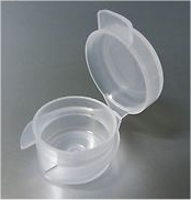
The 5ml plastic sample containers used for thread-trailing have a small hole drilled in them for the thread to run out of. This hole is used for the antenna also. It needs to be TINY to keep the rain out. It is a pain getting the thread through a tiny hole, but more of a pain to deal with a wet transmitter. (hint: carry a needle threader when thread trailing)
Inspect and dry the battery and remove moisture inside the plastic container on every turtle location. (This goes for thread trailing also)
Photo shows the approximate size of the brass or copper battery contact.
A strip of nickel battery tab salvaged from old nicad battery packs will work, too, and doesn't corrode as fast as the brass.
Anyone who has test equipment or breadboarding or prototyping skills and wishing to participate in making this transmitter project better should contact me. I will be willing to share a few different transistors and such.
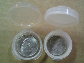
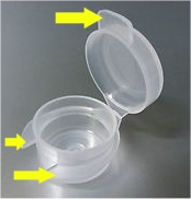
WARNING: Note that a recent Ebay order of 5ml sample vials had a different inside diameter than previous purchase. With the newly purchased vials, neither standard size thead bobbins (for thread trailing), or the above size transmitters fit inside. The photo shows the new and old comparison. To order the correct size vial, look closely at the auction photo and only purchase those that have identical features to the ID photo. A U.S. quarter fits loosely inside the correct size sample container.
The tabs indicated are present on the correct vial.
UPDATE: A number of used AG13 batteries from these transmitters were re-installed in transmitters during the winter, and run to their end. Most powered the transmitters to a total of at least 4 months, and a number were still transmitting past 5 total months. Unfortuately, one battery quit after only 72 days. For the cost of 10 cents per battery, changing them out at 60 or even 30 days is a good idea.
But a foil etch pattern printed on a laser printer and transfered to the board by fusing using a hot iron can also be used.
In this case the etching is done before drilling component holes. It's also a very good idea to spend the time to tin the entire copper foil before mounting the components.
Tinning makes drilling the holes easier, too.
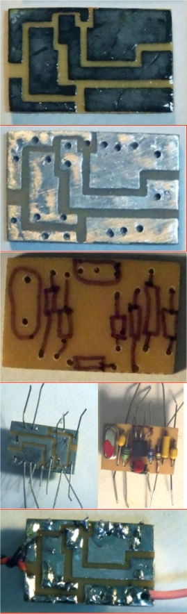
Pattern printed and etched
Board tinned and drilled
Parts placement top
Parts in place ready to be soldered and trimmed
Finished ready for testing
Here is another version of the same transmitter, using an off-board AA or AAA or CR123 lithium battery.
Eastern Box Turtle
Terrapene carolina carolina
A Relict Population Doomed To Extinction?
This version of this transmitter can be made incredibly tiny, even though through-hole components are used.
The crystal is normally the largest part, so to make this radio tiny, a cylinder package should be used, but a small 49 version, including a surface mount package is small also. A tiny surface mount crystal package might have to be mounted on the copper side.
The photos show all components mounted flat to the board, making for a flat finished transmitter. A version could be made with all components standing up, and the board would be very small, but it's finished height would be considerably taller.
A smaller version has also been made using only surface-mount components of the same values, but it takes a lot more effort and precision to solder such tiny parts.